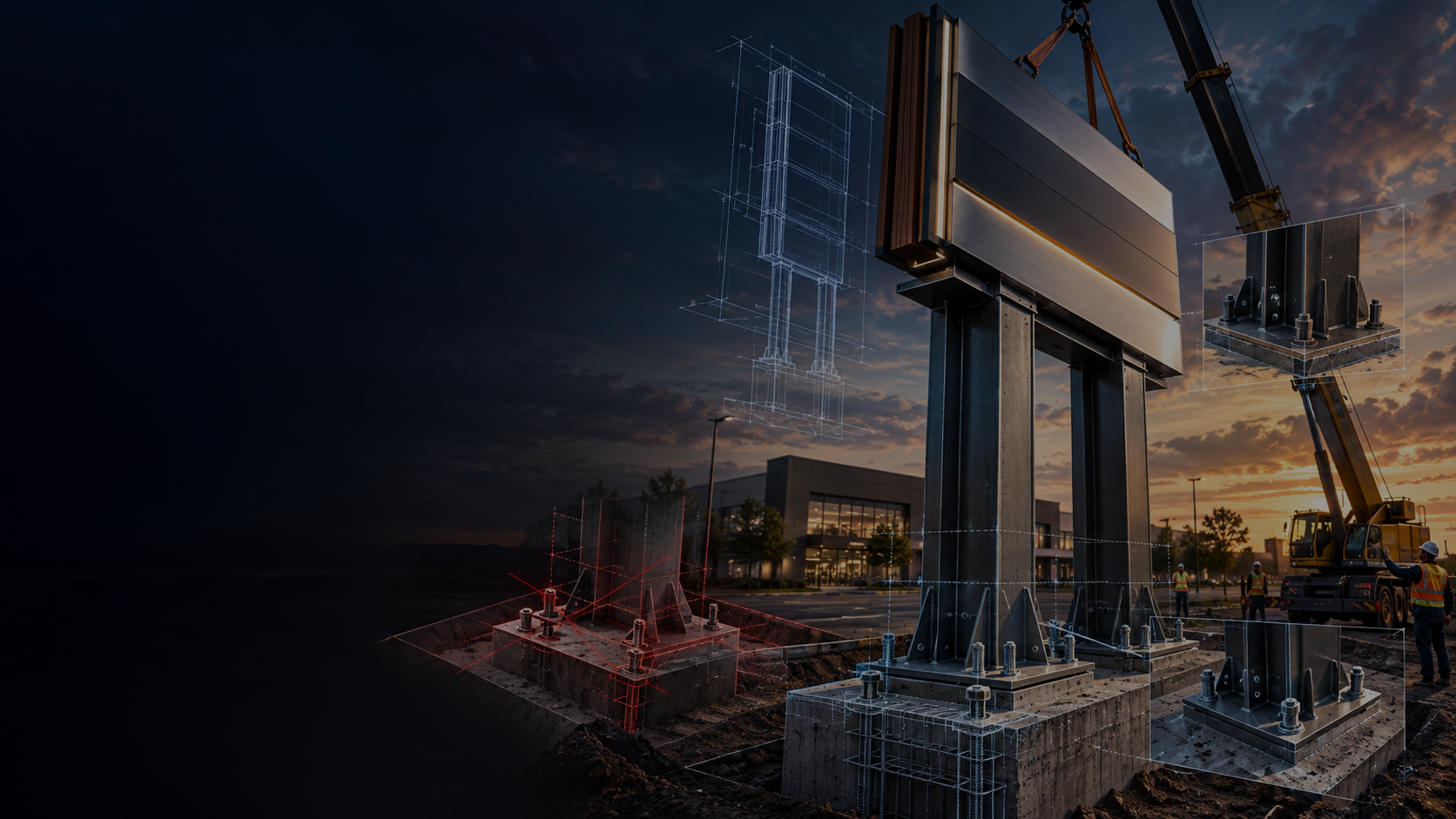
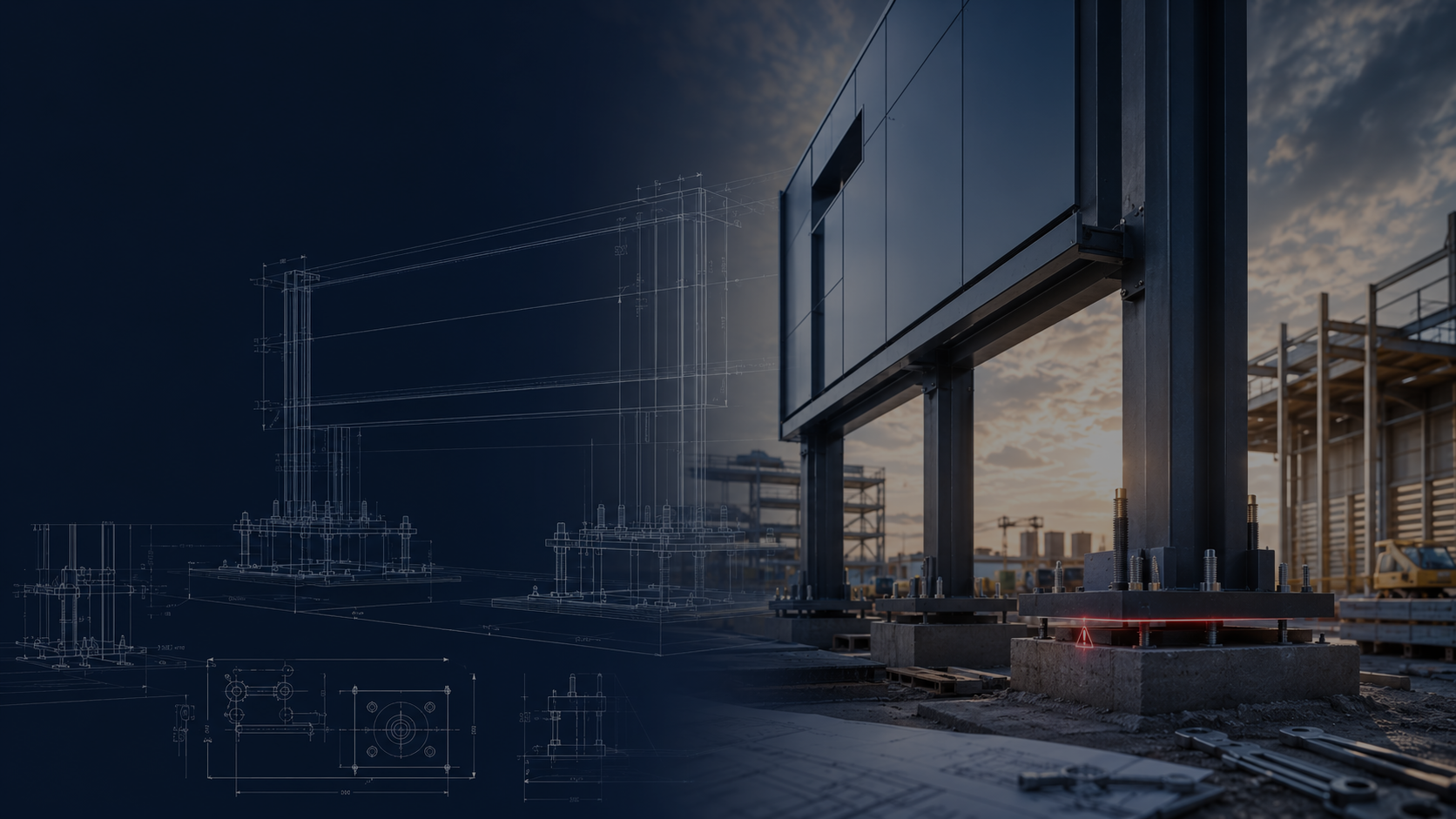
Engineering teams that continue to use 2D CAD drawings find themselves at a crossroads, not necessarily stuck in the past. The transition from flat drafting to full 3D modeling has never been more real, with increasing project complexity, the need for digital documentation, and client expectations for photo-realistic visualizations prior to actual production.
The move from 2D to 3D CAD is more than just a change in technology. It is a fundamental change in how design intent is captured, communicated, and executed. For engineering and manufacturing firms, the decision of when and why to change is crucial.
What is 2D to 3D CAD conversion?

2D to 3D CAD conversion is the process of taking traditional flat engineering drawings, typically created in AutoCAD or similar drafting platforms, and converting them into isometric, 3D models via software applications such as SolidWorks, CATIA, Inventor, Fusion 360, etc.
This conversion means interpreting every dimension, annotation, and projection in the 2D drawings and rebuilding it as a three-dimensional digital model. The result is a geometrically accurate, fully editable 3D representation that can be used for simulation, rendering, CNC programming, and downstream manufacturing processes.
It is a technically demanding scope. Legacy drawings often carry ambiguities, missing views, or outdated tolerances that require engineering judgment, not just CAD skill, to resolve correctly.
The Limitations of 2D Drafting in Modern Engineering
2D CAD has served the engineering world well for decades, but its structural limitations become increasingly costly as product complexity and production speed requirements increase.
In a 2D environment, each part view needs to be built manually and synchronized. When you change one view, you must also change all the other views that depend on it manually. This process is error-prone and time-consuming. There is no spatial intelligence in a flat drawing. In 2D projections, the fabricator must visualize the part's three-dimensional shape in his mind, leaving a lot of room for misinterpretation.
In addition, 2D drawings are not innately supported for design validation workflows. Interference checks, finite element analysis, and tolerance stack-up analysis all require 3D modeling. Teams that rely entirely on 2D documentation are effectively delaying these critical checks until prototyping or production, where errors are exponentially pricier to correct.
When Is the Right Time to Transition?
Operational signals, rather than the mere availability of new technology, should drive the decision to convert from 2D to 3D CAD. Several conditions indicate that conversion has become strategically necessary.

When a component library or product catalog has grown to the point where manual 2D revision management becomes error-prone, 3D modeling offers far greater configuration control. A single master model can control many different versions through design tables. This reduces excess drafting and the chance of version mismatches.
Documentation in 2D only is an impediment to business when clients, OEMs, or manufacturing partners request STEP, IGES, or native 3D file formats as part of their procurement process. The inability to deliver 3D data directly affects the competitiveness in the supplier pre-qualification process.
When a product is being re-engineered, re-manufactured, or adapted for a new application, conversion at that stage allows the team to capture institutional knowledge in a persistent, reusable 3D format rather than reinterpreting aging drawings each time the product is revisited.
3D geometry is essential when validating a design through FEA, CFD, or motion simulation before prototyping. The cost of maintaining a parallel 3D modeling effort just for simulation purposes is substantially higher than converting the full documentation set.
What Makes a CAD Conversion Accurate?
The quality of a 2D to 3D CAD conversion depends almost entirely on the degree of precision applied throughout the engineering workflows. It is not sufficient to simply model the geometry that appears in a 2D drawing. The conversion team is responsible for removing all ambiguities, applying the appropriate tolerances, validating against the original design intent, and producing a model that meets downstream manufacturability requirements.
This process requires that features be designed based on their functional purpose and not just their visual appearance. The hole positions must take the tolerance stack into account. Filets and chamfers shall be indicative of the machining or forming process. Wall thicknesses shall be in accordance with the material specifications of the original design.
Poor conversions result in models that are dimensionally correct but functionally and geometrically incorrect. These models pass visual inspection but fail in assembly, machining, or simulation environments.
Principal Benefits of Converting 2D to 3D CAD
- 3D Associative Modeling: multiple 2D views no longer need to be synchronized manually
- Provides for digital simulation and validation before physical prototyping
- Offers accurate 3D geometry for downstream CNC programming
- Parametric design control reduces the cycles of engineering change orders.
- Enhances client communication with 3D visualization and rendering
- Creates a digital foundation to support product life cycles.
CAD Conversion as a CAD Support Service
For many organizations, the backlog of legacy 2D drawings represents years or decades of accumulated design knowledge. Converting that library in-house demands significant CAD expertise, engineering time, and software investment resources that most teams cannot divert from active product development.
Conversion is available via professional CAD drafting and CAD support services in a systematic, resource-efficient route. An experienced external team can systematically process legacy drawing libraries, apply consistent modeling standards, and deliver validated 3D models for production or simulation use without disrupting internal engineering workflows.
This is not a commodity data-entry task. It requires professionals who understand both the language of 2D drafting and the discipline of 3D parametric modeling and who can make precise engineering decisions when legacy drawings are incomplete or rather ambiguous.
Zealwise Perspective
At Zealwise Technologies, 2D to 3D CAD conversion is treated as a precision engineering service and not a bulk conversion scope. All legacy drawings are checked for completeness, and ambiguities are resolved through client consultation. Every 3D model is validated against the original design intent before final delivery. This results in a conversion output that is geometrically correct, manufacturing-ready, and simulation-capable from day one.
Conclusion
The question of when to switch from 2D to 3D CAD is really a question of where your engineering workflow breaks down under the weight of complexity, client expectations, or production requirements. When 2D documentation can no longer meet the speed and precision demands of contemporary manufacturing, conversion becomes an engineering necessity rather than a choice.
Organizations that invest in accurate, properly executed 2D to 3D CAD conversion position themselves to operate faster, communicate more clearly, and manufacture more reliably. The change costs money up front, but the long-term benefits in terms of design quality, cycle time, and error optimization make it one of the best decisions an engineering organization can make.
FAQs:
1. What is 2D to 3D CAD conversion?
- 2D to 3D CAD conversion is the process of transforming traditional two-dimensional engineering drawings into accurate, editable three-dimensional CAD models. It involves interpreting dimensions, annotations, views, tolerances, and design details from the original drawings and recreating them as a 3D model using professional CAD software.
2. When should a company convert 2D CAD drawings to 3D?
- A company should consider converting 2D drawings to 3D when product complexity increases, manual drawing revisions become difficult to manage, customers require 3D file formats, or the engineering team needs simulation and digital validation. Conversion is also useful when legacy drawings are frequently reused for redesign, manufacturing, or customization.
3. What are the main benefits of 2D to 3D CAD conversion?
- Converting 2D drawings to 3D CAD improves design visualization, revision control, engineering collaboration, and manufacturing readiness. 3D models can also support interference checking, simulation, CNC programming, product visualization, and future design modifications while reducing errors caused by manually coordinating multiple 2D views.
4. Can traditional or legacy 2D engineering drawings be converted into 3D CAD models?
- Yes. Legacy 2D engineering drawings can be converted into 3D CAD models, including older or scanned drawings. However, missing dimensions, unclear annotations, outdated tolerances, or incomplete views may require engineering review and clarification to ensure that the final 3D model precisely complies with the original design intent.
5. How accurate is a 2D to 3D CAD conversion?
- The accuracy of a conversion depends on the quality of the source drawings and the engineering process used to create and validate the 3D model. A professional conversion should verify critical dimensions, tolerances, drill locations, wall thicknesses, fillets, chamfers, and other functional features against the original design requirements & intent.
6. Can converted 3D CAD models be used for manufacturing and simulation?
- Yes. Properly created 3D CAD models can support manufacturing workflows such as CNC programming and fabrication, as well as engineering applications including FEA, CFD, motion simulation, and design validation. The model may require application-specific preparation before you can use it in a particular manufacturing or simulation workflow.
7. Should 2D to 3D CAD conversion be outsourced or done in-house?
- The decision depends on the scale of the legacy drawing library, the availability of in-house CAD expertise, the software resources, project deadlines, and the current workload. Outsourcing can be beneficial when companies have a large backlog of 2D drawings or need specialized CAD resources while their in-house engineering team stays focused on the active project pipeline development.